Introduction to Energy Storage Battery Management System

The battery energy storage system consists of energy storage batteries, a main controller unit (BAMS), individual battery management units (BMU), and a battery pack control and management unit (BCMU).
The BMS uses a 7-inch display screen to show the relevant information of the entire PCS battery pack unit and transmits the relevant information to the monitoring system EMS via Ethernet (RJ45). The information includes individual battery cell information, battery pack information, and battery cluster information.
Uploaded Information: The BMS uploads the following information for individual battery cells (or battery clusters): individual cell voltage, battery pack voltage, charge/discharge current, maximum SOC of individual cells, minimum SOC of individual cells, minimum SOH of individual cells; battery pack SOC, maximum temperature of individual cells, minimum temperature of individual cells, ambient temperature, and related information such as battery abnormal alarms and protection.
Received Information: The BMS receives battery operating parameters from the monitoring system EMS, such as voltage protection settings, alarm settings, temperature protection settings, alarm settings, and SOC protection settings, alarm settings, etc.
The BAMS management server supports the MODBUS communication protocol, where a dedicated protocol point table needs to be defined; the communication interface is network RJ45 communication.
Since the PCS only connects to multiple battery groups, the BMS data is aggregated to the BAMS, and then the BAMS communicates with the PCS, implementing unidirectional transmission, with the BAMS acting as the master and the PCS as the slave.
BMS Information Transmission: The BMS transmits information including battery status parameters and alarm parameters. This includes the battery pack's maximum SOC, minimum SOC, maximum rechargeable capacity, maximum dischargeable capacity, ambient temperature, and minimum SOH. Upon receiving BMS alarm information, the PCS should take appropriate protective actions.
Communication Interface: The PCS and BMS communicate via a CAN or RS485 interface.
Hard Node Information: For timely and reliable protection, the energy storage system reserves hard nodes. When the BMS detects that the battery system has reached its protection limit, the BMS sends the protection limit value to the PCS through the hard node.
The three-layer architecture of the BMS system consists of the single-cell management unit (BMU), the battery pack management unit (BCMU), and the battery cluster (multiple groups) management unit (BAMS); the battery cluster management unit is also called a PCS (Battery Unit Management System).
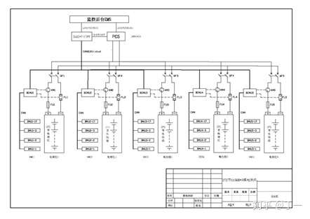
Figure 1. Internal Communication Diagram of the Three-Layer Architecture of Energy Storage BMS
The individual cell management layer is called the BMU, which has one CAN 2.0 bus. It consists of the Battery Acquisition Unit (BCU) and the Battery Balancing Unit (BEU). It collects various individual cell information (voltage, temperature), calculates and analyzes the SOC and SOH of the cells, performs active balancing of individual cells, and uploads individual cell anomaly information to the Battery Cluster Unit Layer (BCMU). It uses CAN 2.0 bus communication externally.
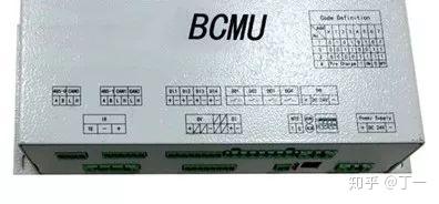
The battery pack management layer is called the BCMU, which has three CAN 2.0 buses and two RS485 (backup) buses. It is responsible for collecting various individual cell information uploaded by the BMU, collecting various information of the battery pack (pack voltage, pack temperature), battery pack charging and discharging current, etc., calculating and analyzing the SOC and SOH of the battery pack, and uploading all information to the Battery Cluster Unit Layer (BAMS). It uses CAN 2.0 bus communication.
The battery cluster management layer is called BAMS, which has one Ethernet port, two CAN 2.0 buses, and one RS485 (backup) bus. It is responsible for collecting various battery information uploaded by the BCMU and uploading all information to the energy storage monitoring EMS system via an RJ45 interface; it also communicates with the PCS, sending relevant battery anomaly information to the PCS (CAN or RS485 interface), and is equipped with a hardware dry contact for the PCS.
The battery energy storage system (BMS) focuses on two main aspects: battery data analysis and calculation, and battery balancing.
The battery management system provided by the energy storage power station features bidirectional active lossless balancing, with a maximum balancing current of 5A and a balancing efficiency exceeding 80%. It effectively identifies and alerts users to abnormal individual cells for replacement, rapidly and efficiently improving battery pack consistency, increasing battery pack utilization and lifespan, and ensuring the normal operation of the entire energy storage system.Individual Battery Balancing Unit:
Due to manufacturing processes and other factors, individual batteries exhibit variations in capacity and performance. During the charging and discharging process of the battery pack, these variations inevitably increase. During charging, batteries with smaller capacity and lower performance may overcharge; during discharging, they may over-discharge. This leads to a decreasing battery pack capacity utilization rate, and over time, this vicious cycle accelerates battery damage. Therefore, the need for balancing circuits in power and energy storage battery packs to extend battery life is a consensus among scholars and industry professionals both domestically and internationally.

Figure 2. Schematic diagram of battery balancing function
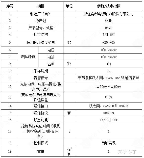
BAMS is a platform built with a high-performance 32-bit MCU processor, embedded with a Linux operating system, and features a built-in 7-inch TFT touch LCD display. It can upload lithium battery energy storage system data to the backend management system in real time and receive monitoring from the backend. Independently developed, it supports function expansion and customized services. BAMS communicates with the microgrid central control system via Ethernet Modbus TCP/IP, and with the PCS via RS-485, using the Modbus protocol. Through a remote server via Ethernet, the battery energy storage system can be monitored and managed in real time, enabling telemetry, remote signaling, and remote control. This allows for timely maintenance of the energy storage system, ensuring its safe operation and improving the reliability of the power supply system.

Figure 3 interface
Table 1 Technical Specifications of Energy Storage System Management Unit (BAMS)

Main Functions of Energy Storage Battery Management Module
Ø Online automatic detection of individual battery voltage and temperature; Online 2A lossless equalization enables charging equalization; Real-time alarm function provides over-limit alarms for voltage and temperature; On-site alarm: when the dry contact output is closed, remote computer alarm and alarm content display are possible; Equipped with an RS485 communication interface, it can be connected to a monitoring system or on-site data acquisition unit to transmit data and alarm information, achieving remote monitoring of the battery pack; Modular design with isolation between modules ensures high system reliability. Key Specifications of the Energy Storage Battery Management Module:
Main Specifications of the Energy Storage Battery Management Module:
Module Power Supply Voltage: DC 24V ±10%
Number of Battery Cells Monitored: 16
Voltage Detection Range: 0~5.0 V
Voltage Detection Accuracy: ±0.1%FSR
Temperature Measurement Accuracy: ±1℃
Lossless Balancing Current: 2A
Battery Balancing Method:
Active lossless charging equalization Input insulation resistance: ±5MΩ 500V Data communication interface: RS485 or CAN2.0 Communication baud rate: 9600bps or 250kbps Field display method: LED working status indicator Dimensions and weight: 250×126×45(mm)/1Kg Installation method: Rack mount, wall mount(A) Equalization System Working Principle Explanation:
u Battery Information Acquisition:
Fast and accurate battery information acquisition is the foundation for effective equalization; the energy storage battery management module adopts a high-speed, high-precision, high-effective-bit Sigma-Delta 24-bit AD converter, and a high-precision (±0.05%) low-temperature drift (±2PPM) precision reference, ensuring high consistency and accuracy of battery information measurement under any permissible working environment.
u Equalization Rule Calculation:
Equalization rules identify which batteries need to be equalized and how to equalize them; superior equalization rule calculation is the guarantee of effective equalization.
The balancing rules of the energy storage battery management module integrate factors such as battery pack status, battery voltage, battery SOC, temperature, battery manufacturer, and cycle count, making the calculation results more in line with actual needs and enabling discharge, charging, and dynamic balancing.
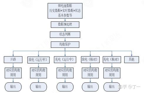
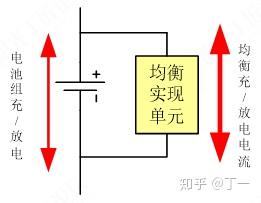
Figure 5. Schematic diagram of equalization implementation
u Equalization effect:
Battery pack charging stage:
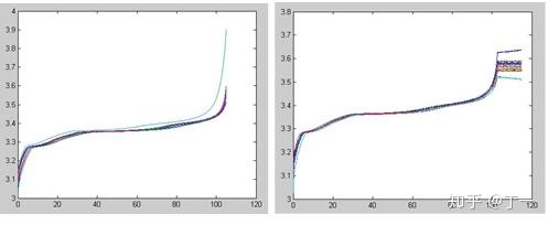
Original charging curve without balancing system; Charging curve with balancing system
Battery pack discharge stage:
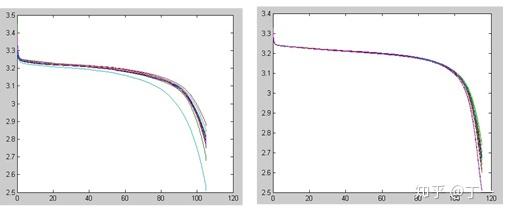
Figure 5: Original discharge curve without balancing system; discharge curve with balancing system
After using the energy storage battery management module to manage the balancing system, the consistency of each individual battery cell during charging and discharging is greatly improved, and the lithium battery pack is effectively balanced.
The battery pack control unit collects real-time data on the voltage and current of the entire battery pack, controls the DC circuit switching, monitors the status of on-site alarm devices in real time, and uploads the data to the energy storage system management unit.
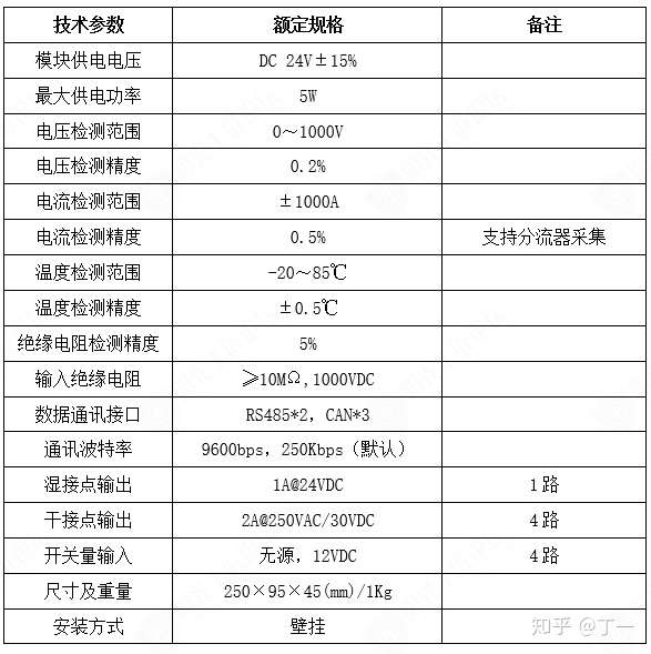
Main functions of the energy storage battery pack control module:
Ø Automatic online detection of battery pack voltage, current, and ambient temperature; Features DC circuit on/off function; Real-time alarm function for over-limit alarms on the entire battery pack's voltage and current; On-site alarm and switch quantity detection function, enabling remote computer alarm and display of alarm content; Features 3 CAN and 2 RS485 communication interfaces, allowing connection to a Battery Cluster Management Unit (BAMS) for data and alarm information transmission, achieving remote monitoring of the battery pack.
Main Indicators of the Energy Storage Battery Pack Control Module: