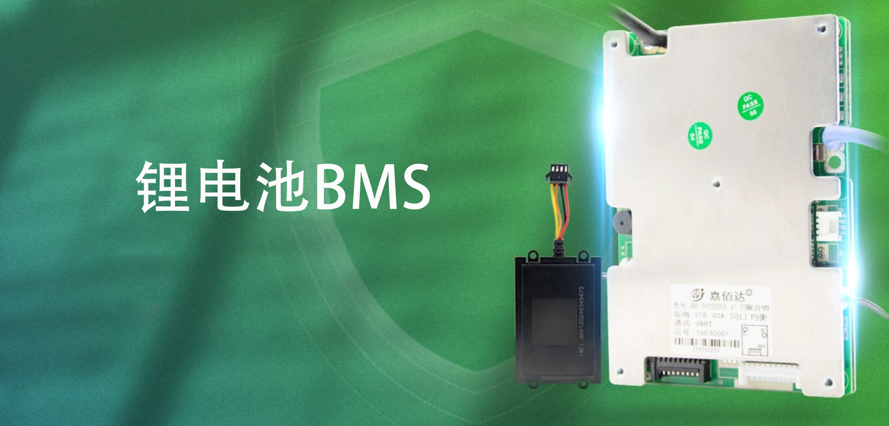
Lithium battery materials have certain characteristics that prevent them from being overcharged, over-discharged, over-currented, short-circuited, or subjected to extremely high and low temperature charging and discharging. Therefore, lithium battery packs are always accompanied by a sophisticated BMS (Battery Management System), also known as a protection board.
I. BMS Functions
First, we will detail its four main functions.
(I) Sensing and Measurement: Sensing the Battery's State
This is a basic function of the BMS, including the measurement and calculation of several indicators and parameters, including voltage, current, temperature, charge, SOC (state of charge), SOH (state of health), SOP (state of power), and SOE (state of energy).
SOC can be simply understood as how much charge the battery has left, with a value between 0-100%. This is the most important parameter in the BMS; SOH refers to the battery's health state (or the degree of battery degradation), which is the ratio of the battery's actual capacity to its rated capacity. When the SOH is below 80%, the battery cannot be used in a power environment.
(II) Alarms and Protection When the battery exhibits an abnormal state, the BMS can send an alarm to the platform, protect the battery, and take corresponding measures. Simultaneously, it will send the abnormal alarm information to the monitoring and management platform and generate alarm messages of different levels. For example, if the temperature overheats, the BMS will directly disconnect the charging and discharging circuit for overheat protection and send an alarm to the backend. Lithium batteries will primarily issue warnings for the following issues: Overcharge: Individual cell overvoltage, total voltage overvoltage, charging overcurrent; Over-discharge: Individual cell undervoltage, total voltage undervoltage, discharging overcurrent; Temperature: Cell temperature too high, ambient temperature too high, MOSFET temperature too high, cell temperature too low, ambient temperature too low; **State:** Water immersion, impact, inversion, etc. **(III) Balance Management** **The necessity of balance management stems from the inconsistencies in battery production and use.** **From a production perspective:** Each battery has its own lifecycle and characteristics; no two batteries are exactly alike. Due to inconsistencies in materials such as separators, cathodes, and anodes, the capacities of different batteries cannot be completely identical. For example, the voltage difference, internal resistance, and other consistency indicators of the cells that make up a 48V/20AH battery pack all vary within a certain range. From a usage perspective, the electrochemical reactions during battery charging and discharging can never be perfectly uniform. Even within the same battery pack, variations in temperature and impact can cause differences in charge/discharge rates, resulting in inconsistent cell capacities. Therefore, batteries require both passive and active balancing. This involves setting thresholds for initiating and ending balancing: for example, balancing might begin when the difference between the extreme voltage of a single cell and the average voltage of the entire pack reaches 50mV, and end when it reaches 5mV.
(IV) Communication and Positioning
The BMS has a separate communication module, whose functions are data transmission and battery positioning, and it can transmit the relevant sensed and measured data to the operation management platform in real time.
II. BMS Protection Working Principle
BMS includes a control IC, MOS switches, fuses, NTC thermistors, TVS transient voltage suppressors, capacitors, and memory, etc. Its specific form is shown in the figure:
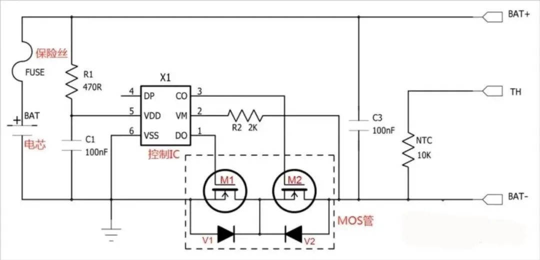
In the diagram above, the control IC controls the MOS switches to turn the circuit on and off, thus protecting the circuit. The FUSE provides secondary protection based on this. TH is for temperature detection, internally containing a 10K NTC. The NTC primarily performs temperature detection. The TVS mainly suppresses surges.
(I) Primary Protection Circuit
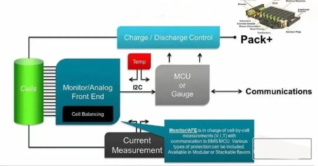
The control IC in the diagram above is responsible for monitoring the battery voltage and loop current, and controlling the switches of the two MOS switches. The control IC can be specifically divided into AFE and MCU:
The AFE (Active Front End, analog front-end chip) is the battery sampling chip, mainly used to collect cell voltage, current, etc.
The MCU (Microcontroller Unit, microcontroller chip) mainly performs calculations and controls based on the information acquired by the AFE.
The relationship between the two is shown in the figure:
1.AFE
AFE is generally a 6-pin chip, with CO, DO, VDD, VSS, DP, and VM, briefly described below:
CO: Charge Output (Charging Control);
DO: Discharge Output (Discharging Control);
VDD: Power Supply Voltage, also called Output Voltage, is the highest voltage point;
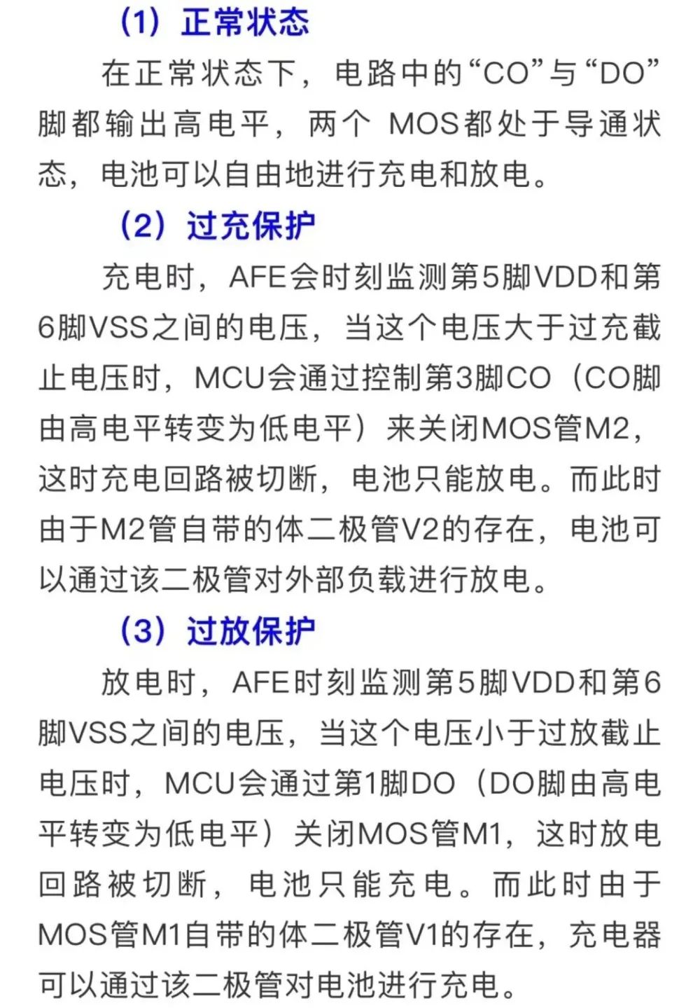
If a lithium battery is overcharged, over-discharged, or over-currented, it will cause chemical side reactions inside the battery, severely affecting its performance and lifespan. It may also generate a large amount of gas, causing a rapid increase in internal pressure, eventually leading to the pressure relief valve opening, electrolyte ejection, and thermal runaway.
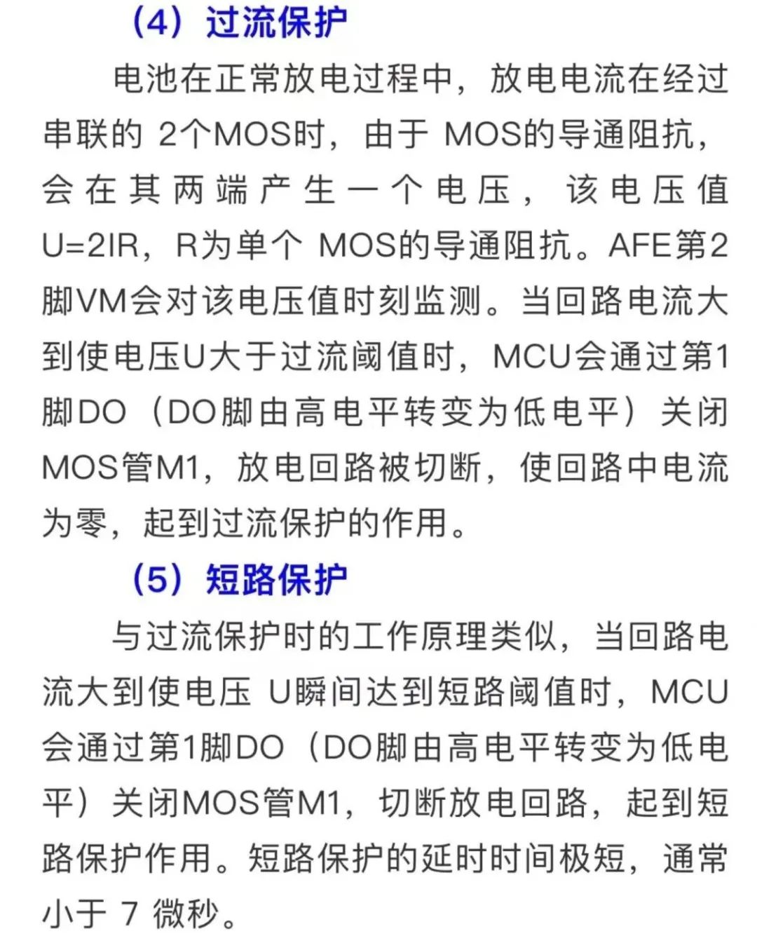
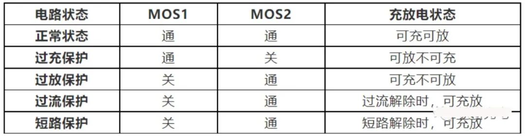
In the event of the above situation, the BMS will activate the protection mechanism and execute the following:
以上内容可以简述为:
(II) Secondary Protection Circuit: Three-Terminal Fuse
For safety reasons, a secondary protection mechanism is still needed. Currently, REP (Resistor Embedded Protector) is widely used, while the three-terminal fuse offers better cost-effectiveness.
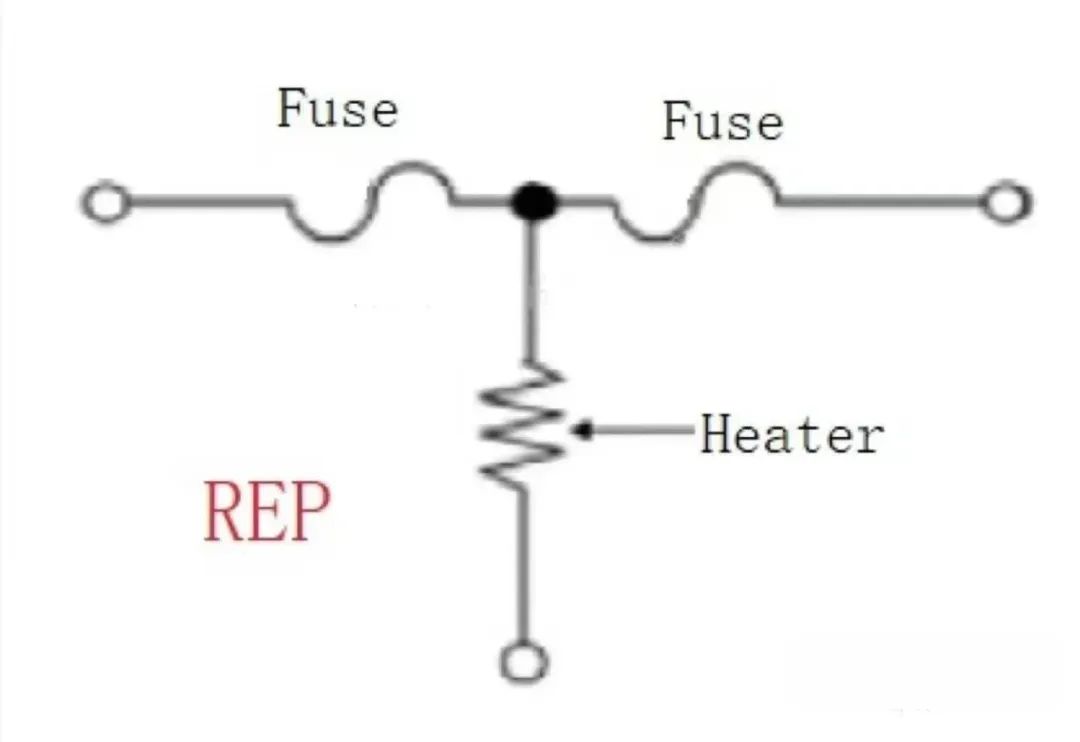
When the current is too high, the fuse works the same way as a regular fuse and will melt; however, when the MOS operates abnormally, the main controller will actively melt the three-terminal fuse.
The advantages of this safety protection mechanism are mainly low power consumption, fast response speed, and good protection effect. It is currently highly applicable and widely used in electric vehicles, mobile phones, and other devices.
(III) Three-level protection circuit: NTC and TVS
1. NTC thermistor
A thermistor, as the name suggests, is extremely sensitive to heat. It is a type of variable resistor, mainly divided into PTC and NTC types.
PTC (Positive Temperature Coefficient) thermistors have a higher resistance as the temperature increases, and are mainly used in products such as mosquito killers and heaters.
NTC (Negative Temperature Coefficient) thermistors, on the other hand, have a lower resistance as the temperature increases, and are mainly used as resistance temperature sensors and current limiting devices.
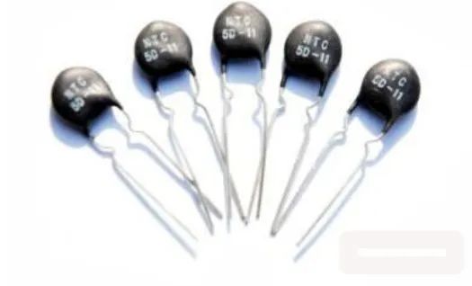
Lithium-ion batteries generally use NTC in their BMS (Battery Management System). Compared to NTC, this product consumes less power, has higher accuracy, and responds quickly, mainly serving three purposes.
(1)Temperature Measurement
Utilizing the characteristics of this resistor, the following three temperature ranges can be measured:
Cell Temperature: To measure the cell temperature, the number of cells covered by each NTC needs to be considered.
Power Temperature: To measure the power temperature, the NTC thermistor is placed between the MOS devices. During installation, it is necessary to ensure that the NTC is in close contact with the MOS devices.
Ambient temperature: Place the NTC thermistor on the BMS board to measure the ambient temperature. The installation location should be far away from power devices.
(2)Temperature Compensation
The resistance of most components increases with temperature. In this case, NTC compensation is needed to offset the temperature-induced error.
(3)Suppressing Surge Current
An electrical surge, also called a transient surge, is a peak value that appears instantaneously beyond the stable value, including surge voltage and surge current.
Electronic circuits generate large surge currents when powered on, which can easily damage components. Using NTC can prevent this from happening and ensure the normal operation of the circuit. For surge protection, TVS is required.
2. TVS Transient Voltage Suppressor
TVS (Transient Voltage Suppressors) are fast-responding devices suitable for port protection. The specific implementation is as follows:
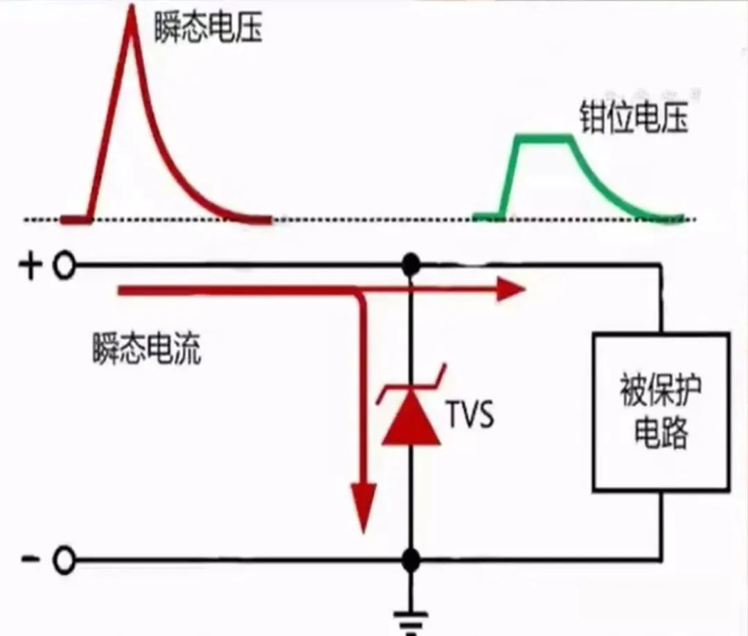
When an abnormally high voltage occurs in the circuit, the TVS will quickly adjust its resistance state to release the instantaneous current to ground, protecting the downstream circuit from damage; after the abnormal voltage situation ends, the TVS will return to its original state.
III. Localization of Key BMS Components
Currently, there is a severe lack of research on related core chips in the domestic BMS manufacturing process, especially AFE chips. CATL Chairman Zeng Yuqun once stated that CATL does not directly involve American technology, materials, or equipment in its battery production process; currently, the only thing it relies on from the US is the chips in its BMS.
(I) AFE Analog Front-End Chips
In terms of market share, the United States accounts for 70% of the global AFE chip market, with Analog Devices and Texas Instruments alone accounting for about 60%. Among domestic chip manufacturers, the fastest-growing are Chipown Microelectronics, Chipsea Technologies, and Silergy.
(II)MCU Chips
Regarding MCU chips, the market share is mainly occupied by companies from Europe, the United States, Japan, and Taiwan. NXP, Microchip, STMicroelectronics, and Infineon alone account for over 80% of the market share. Mainland Chinese companies have a very small market share, with only GigaDevice and Extreme Ocean Semiconductor showing relatively rapid growth.
(II)MCU Chips
IV. BMS Issues and Optimization Directions
BMS is not just the responsibility of BMS R&D manufacturers; it is a systems engineering project that requires the joint participation of cell manufacturers, BMS manufacturers, PACK manufacturers, and especially battery swapping operators.
(I) Battery Swapping Operators
As the management and control system for lithium batteries, BMS essentially refines, summarizes, and solidifies operational experience based on user needs into the BMS. Battery swapping operators are closest to users and understand their needs best; therefore, they are the leaders in BMS implementation.
(II) BMS Manufacturers BMS manufacturers have the best understanding of electronic circuits. Based on cell performance and the needs of battery swapping operators, they build and develop BMS architectures, playing a crucial role in bridging the gap between upstream and downstream processes. However, their weaknesses are also prominent, mainly manifested in an insufficient depth of understanding of battery cells, leading to discrepancies between control strategies and the actual situation of the cells. (III) Cell Manufacturers Cell manufacturers have the best understanding of chemistry, which is actually the foundation of the entire BMS control system, as all BMS control is based on the cells and battery packs. However, currently, cell manufacturers still need to improve their understanding of electronic circuits, such as which information collection method can collect the most accurate cell information. (IV) PACK Manufacturers PACK manufacturers assemble battery cells and BMS into battery packs. Their work, including cell arrangement, BMS placement, and assembly processes, significantly impacts the functionality and accuracy of the BMS. PACK manufacturers, based on the requirements of battery swapping operators, must impose specific requirements on cell and BMS manufacturers from a final quality control perspective. Therefore, the design of BMS protection logic relies on the accumulation and solidification of operational experience. Effective implementation of this protection logic requires cell-based circuit design and improved product cost-effectiveness. Battery cell manufacturers, BMS manufacturers, and PACK manufacturers, under the guidance of battery swapping operators, must not only perform their respective professional duties but also collaborate effectively to form a cohesive force for BMS product system integration. This is the inevitable path for future BMS development and problem-solving.