By inverting the rectifier circuit, one end is connected to direct current (DC), and the other end can be connected to alternating current (AC).This is an inverter, a device that converts direct current to alternating current.
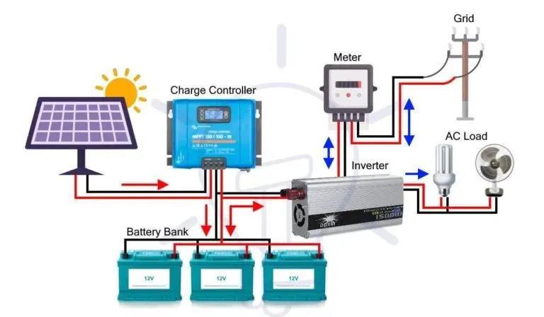
Most commercial, industrial, and residential loads require AC power, but AC power cannot be stored in batteries, and battery storage is important for backup power. Today, this shortcoming can be overcome with DC power.
The polarity of DC power does not change over time like AC power, therefore DC power can be stored in batteries and supercapacitors. So we can first convert AC to DC and then store it in batteries. This way, whenever AC power is needed to operate AC appliances, the DC power will be converted back to AC power to operate the AC appliances.
Based on the input source, connection method, output voltage waveform, etc., inverters are divided into the following 17 main categories.
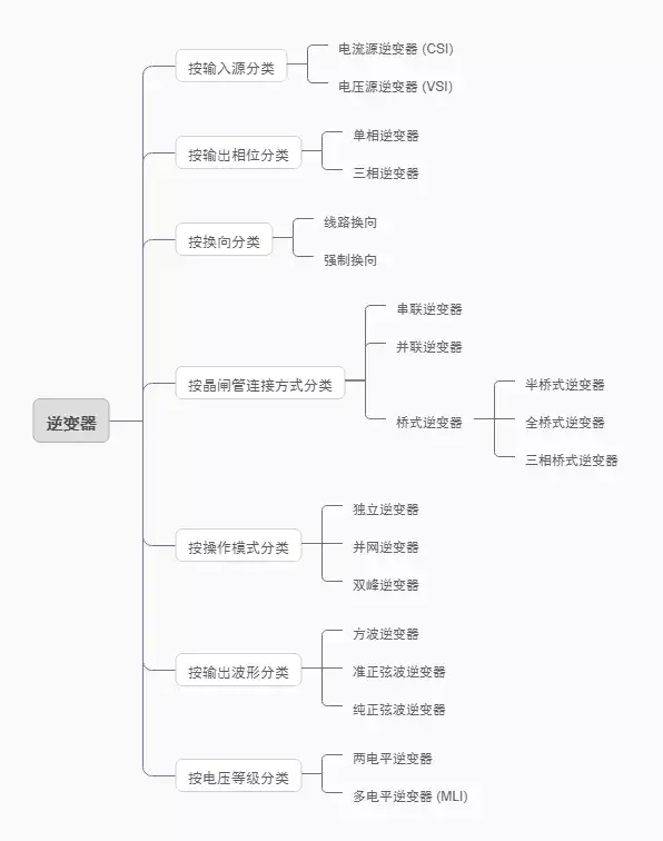
Inverter Classification, Source: Huaqiu Mall
I. Classification by Input Source
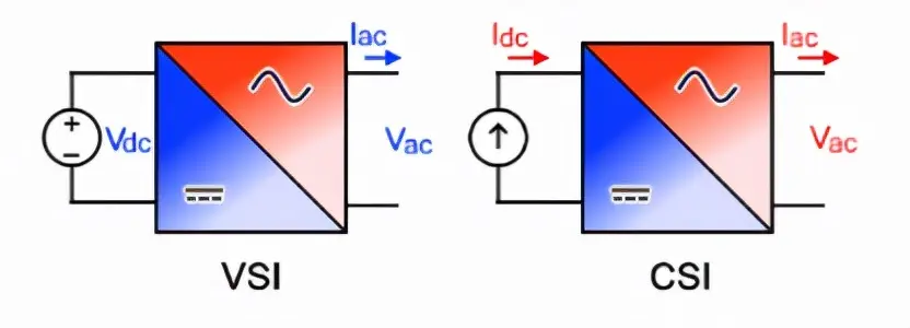
Inverters can be classified by voltage or current source, hence they are divided into voltage source inverters (VSI) and current source inverters (CSI).
Voltage Source Inverter (VSI)
When the input of an inverter is a constant DC voltage source, the inverter is called a voltage source inverter.
The input of a voltage source inverter has a rigid DC voltage source with zero impedance. In practice, the impedance of the DC voltage source can be ignored. Assuming that the VSI is powered by an ideal voltage source (an extremely low impedance source), the AC output voltage is entirely determined by the state of the switching devices in the inverter and the applied DC power supply.
Current Source Inverter (CSI)
When the input of an inverter is a constant DC current source, the inverter is called a current source inverter.
Rigid current is supplied to the CSI from a DC power supply with high impedance. Typically, a large inductor or closed-loop control current is used to provide the rigid current. The resulting current waveform is rigid and unaffected by the load. The AC output current is entirely determined by the switching devices in the inverter and the state of the DC power supply applied.
II. Classification by Output Phase
Based on the output voltage and current phase, inverters are mainly divided into two categories: single-phase inverters and three-phase inverters.
Single-phase inverter
A single-phase inverter converts a DC input to a single-phase output. The output voltage/current of a single-phase inverter is only one phase, with a nominal voltage at a nominal frequency of 50Hz or 60Hz.
Nominal voltage is defined as the voltage level at which an electrical system operates. There are different nominal voltages: 120V, 220V, 440V, 690V, 3.3KV, 6.6KV, 11kV, 33kV, 66kV, 132kV, 220kV, 400kV, and 765kV. Lower nominal voltages can be achieved directly using an inverter with an internal transformer or step-up/step-down circuit, while higher nominal voltages require an external step-up transformer.
Single-phase inverters are used for low loads. Single-phase losses are higher, and single-phase efficiency is lower than that of three-phase inverters. Therefore, three-phase inverters are the preferred choice for high loads.
Three-phase inverters
A three-phase inverter converts direct current (DC) to three-phase power. Three-phase power provides three AC currents with uniformly separated phase angles. All three waves generated at the output have the same amplitude and frequency, but vary slightly due to the load, and each wave has a 120-degree phase shift from one to the other.
Basically, a single three-phase inverter is three single-phase inverters, each with a 120-degree phase difference, and each single-phase inverter is connected to one of the three load terminals.
III. Classification by Commutation Technology
Based on commutation technology, inverters can be mainly divided into two types: line-commutated and forced-commutated inverters. In addition, there are auxiliary-commutated inverters and complementary-commutated inverters, but since they are not commonly used, we will briefly discuss the two main types here.
Line Commutation
In these types of inverters, the line voltage of the AC circuit can be obtained through the device; when the current in the SCR experiences zero characteristics, the device is turned off. This commutation process is called line commutation, and inverters operating based on this principle are called line-commutated inverters.
Forced Commutation
In this type of commutation, the power supply does not reach a zero point. This is why an external source is needed to rectify the power supply. This commutation process is called forced commutation, and an inverter based on this process is called a forced commutation inverter.
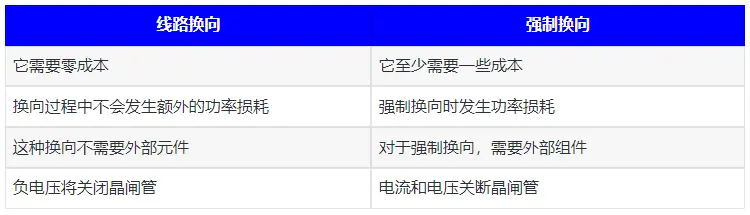
Comparison of Two Types of Commutation Inverters
IV. Classification by Connection Method
Based on the connection method of the thyristors in the circuit, inverters can be divided into series inverters, parallel inverters, and bridge inverters. Bridge inverters are further divided into half-bridge, full-bridge, and three-phase bridge inverters.
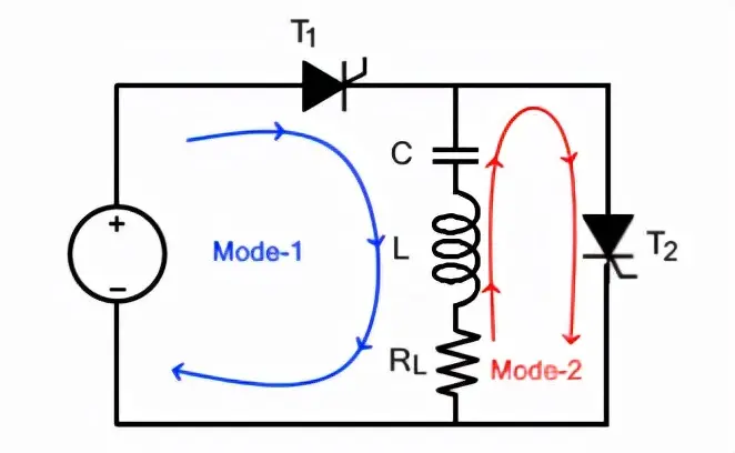
Series Inverters
A series inverter consists of a pair of thyristors and an RLC (resistor, inductor, and capacitor) circuit. One thyristor is connected in parallel with the RLC circuit, and the other thyristor is connected in series between the DC power supply and the RLC circuit.
This type of inverter is called a series inverter because the load is directly connected in series with the DC power supply with the help of thyristors. A series inverter is also called a self-commutated inverter because the thyristors in this type of inverter are commutated by the load itself. Another name for this inverter is "load-commutated inverter." This name is given because the LCR is the load that provides commutation.
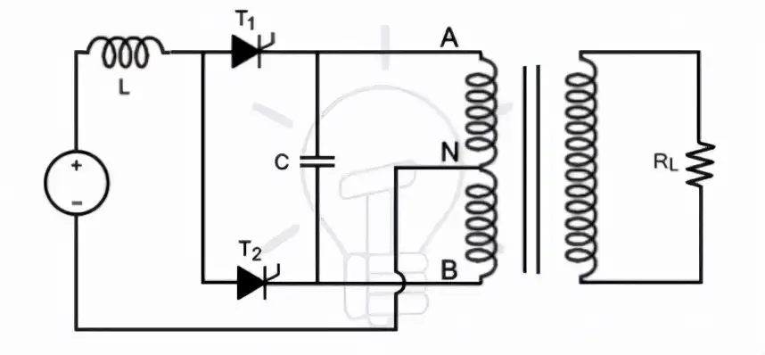
Parallel Inverter
A parallel inverter consists of two thyristors, a capacitor, a center-tapped transformer, and an inductor. The thyristors provide a path for current flow, while the inductor keeps the current source constant. The switching on and off of these thyristors is controlled by a commutation capacitor connected between them.
It is called a parallel inverter because, in operation, the capacitor is connected in parallel with the load through the transformer.
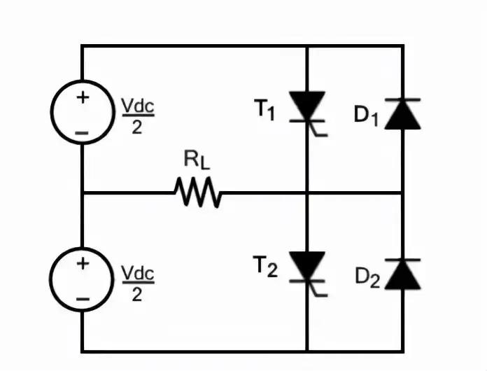
Half-bridge Inverter
A half-bridge inverter requires two electronic switches to operate. These switches can be MOSFETs, IJBTs, BJTs, or thyristors. A half-bridge with thyristor and BJT switches requires two additional diodes, except for purely resistive loads, while MOSFETs have built-in body diodes. In short, two switches are sufficient for purely resistive loads, while other loads (inductors and capacitors) require two additional diodes. These diodes are called feedback diodes or freewheeling diodes.
The operating principle of a half-bridge inverter is the same for all switches, but here we discuss a half-bridge with thyristor switches. There are two complementary thyristors, meaning one thyristor is turned on at a time. For resistive loads, the circuit operates in two modes. The switching frequency will determine the output frequency.
When the output frequency is 50Hz, each thyristor conducts for 20ms at a time.
Full-bridge Inverter
A single-phase full-bridge inverter has four controlled switches to control the direction of current flow in the load. The bridge has four feedback diodes that feed the energy stored in the load back to the power source. These feedback diodes only function when all thyristors are off and the load is not purely resistive.
For any load, only two thyristors operate at a time. Thyristors T1 and T2 will conduct in one cycle, while T3 and T4 will conduct in another cycle. In other words, when T1 and T2 are ON, T3 and T4 are OFF, and when T3 and T4 are ON, the other two are OFF. Turning on more than two thyristors at once will cause a short circuit, generating excessive heat and immediately burning out the circuit.
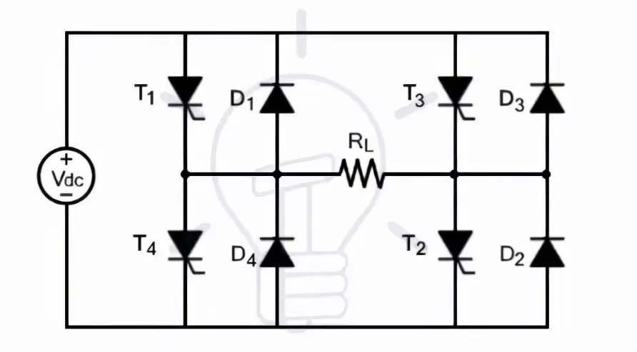
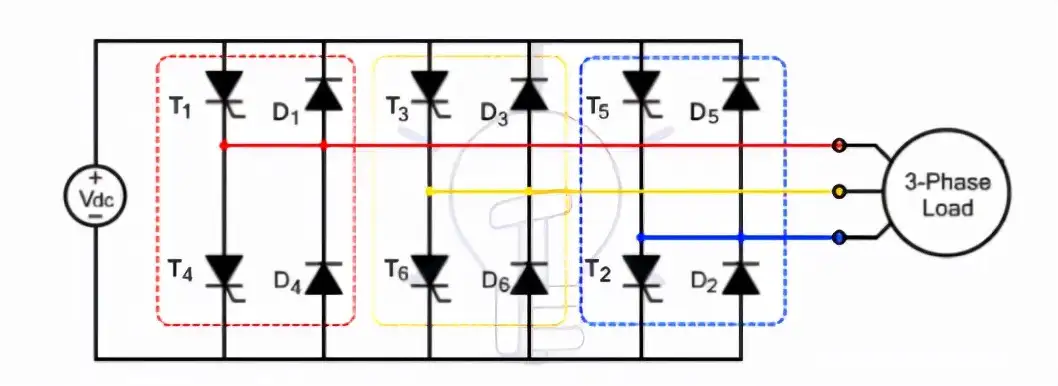
Three-phase bridge inverter
Industrial and other heavy loads require three-phase power. To run these heavy loads from storage devices or other DC power sources, a three-phase inverter is needed. A three-phase bridge inverter can be used for this purpose.
A three-phase bridge inverter is another type of bridge inverter, consisting of 6 controlled switches and 6 diodes, as shown in the figure.
V. Classification by Operating Mode
According to the operating mode, inverters are divided into three main categories:
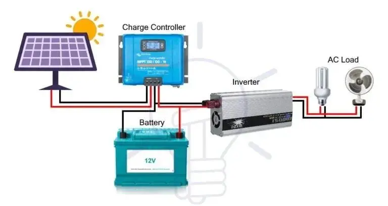
Standalone Inverters
Standalone inverters are directly connected to the load and are not interrupted by other power sources. Standalone inverters, or "off-grid mode inverters," supply power to the load independently without being affected by the grid or other power sources.
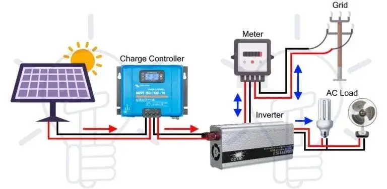
These inverters are called off-grid inverters because they are not affected by the public power grid. These inverters cannot be connected to the public grid because they lack synchronization capabilities, where synchronization is the process of matching the phase and nominal frequency (50/60 Hz) of two AC power sources. Grid-connected Inverters (GTIs) have two main functions. One function of a grid-connected inverter is to supply AC power from storage devices (DC power sources) to AC loads, while the other function is to supply additional power to the grid. Grid-connected inverters, also known as utility-interactive inverters, grid-connected inverters, or grid feedback inverters, synchronize the frequency and phase of the current to adapt to the public power grid. Power is transferred from the DC power source to the utility grid by increasing the voltage level of the inverter.
Twin-Peak Inverter
Twin-peak inverters can operate as both grid-connected and stand-alone inverters. These inverters can inject additional energy from renewable energy sources and storage devices into the grid, and recover power from the grid when renewable energy generation is insufficient. In other words, these inverters can operate as both stand-alone and grid-connected inverters depending on load requirements. Twin-peak inverters are multifunctional, encompassing the functions of both stand-alone and grid-connected inverters.
Once renewable energy begins to generate additional energy, the operating mode changes from stand-alone mode to grid-connected mode. The inverter synchronizes its phase and frequency with the grid and begins to inject additional energy into the grid.
VI. Classification by Output Waveform
An ideal inverter is one that converts a DC signal into a pure sinusoidal AC output. The problem with practical inverters is that their output signal is not pure sinusoidal. Based on the output waveform, inverters are divided into three main categories:
Square Wave Inverters
These are the simplest inverters that convert DC to AC, but the output waveform is not the desired pure sine wave. These inverters have a square wave at the output. In other words, these inverters convert DC input to AC in the form of a square wave. Square wave inverters are also cheaper.
The simplest structure of these inverters can be an H-bridge inverter.
As shown in the figure, a simpler version can be achieved by using an SPDT (single push double throw) switch before the transformer. This transformer will also help achieve any desired output voltage level.
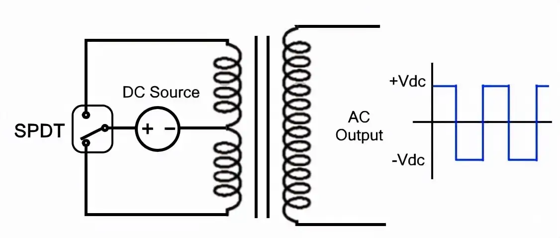
The operation of the given model is extremely simple. Simply turning the switch on and off simultaneously changes the current at the output. In other words, switching a single-pole double-throw inverter at the desired frequency will generate an AC square wave at the output of a typical inverter (i.e., a center-tapped transformer). A typical sine wave has a harmonic distortion of about 45%, which can be further reduced by using a filter to remove some harmonics.
Quasi-sine wave inverter
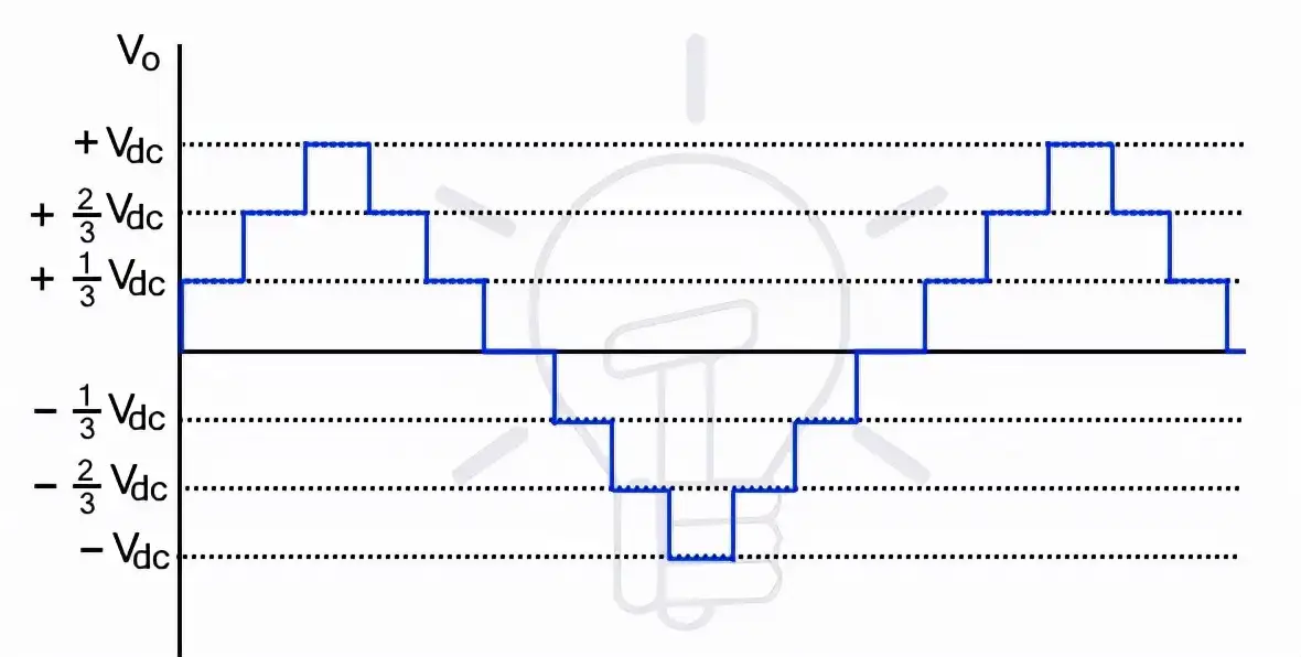
Quasi-sine wave inverters, or simply modified sine wave inverters with stepped sine waves, are inverters whose output signal gradually increases with positive polarity. After reaching a positive peak, the output signal gradually decreases until it reaches a negative peak, as shown in the figure.
The structure of a quasi-sine wave inverter is much simpler than that of a pure sine wave inverter, but more complex than that of a pure square wave inverter.
Although the final output waveform of these inverters is not a pure sine wave, the harmonic distortion of the output is still reduced to 24%. Filtering further reduces distortion, but the amount of distortion is still significant. For this reason, these inverters are not the first choice for driving a variety of loads, including electronic circuits.
Quasi-sine waves can permanently damage electronic devices with timers in the circuit. If connected to a quasi-sine wave inverter, all appliances with motors will not work as efficiently as when connected to a pure sine wave inverter. Furthermore, the rapid waveform transitions can introduce noise. Due to these problems, the application of quasi-sine wave inverters is limited.
Pure Sine Wave Inverter
A pure sine wave inverter converts DC to near-pure sinusoidal AC. While the output waveform of a pure sine wave inverter is still not an ideal sine wave, it is much smoother than that of square wave and quasi-sine wave inverters.
The output waveform of a pure sine wave inverter has extremely low harmonics. Harmonics are sine waves with odd multiples of the fundamental frequency and varying amplitudes. Harmonics are highly undesirable because they can cause serious problems in various electrical appliances. These harmonics can be further reduced by using various PWM techniques and then passing the output signal through a low-pass filter.

Pure sine wave inverters are much more complex to construct and operate than square wave and quasi-sine wave inverters.
These inverters are superior to the previous two types because most electrical equipment requires a pure sine wave to operate better. As mentioned earlier, square wave or quasi-sine wave inverters can damage electrical appliances, especially those with motors. Therefore, for practical applications, pure sine wave inverters are used.
VII. Classification by the Number of Output Levels
Any inverter can have at least two or more output levels. Based on the number of output levels, inverters are divided into two categories: two-level inverters and multi-level inverters.
Two-level Inverter
A two-level inverter has two output levels. The output voltage alternates between positive and negative, and at a fundamental frequency (50Hz or 60Hz).
Some so-called "two-level inverters" have three levels in their output waveform. Three-level inverters are classified as such because one of the levels is zero voltage. In reality, zero is the third level, but it is still classified as a two-level inverter.
A two-level inverter circuit consists of a source and several switches that control the current or voltage. Due to switching losses and limitations in device ratings, two-level inverters are limited in high-frequency operation in high-voltage applications. However, the switch ratings can be increased through series and parallel combinations.
In a two-level inverter, the set of switches providing the positive half-cycle is called the positive group, and the other set providing the negative half-cycle is called the negative group.Two-level inverters are not preferred for the following reasons: Inverters need to operate with a minimum number of switches and a minimum power supply to convert power in small voltage steps. Smaller voltage steps will provide a high-quality waveform. Furthermore, it can reduce voltage (dv/dt) stress on the load and electromagnetic compatibility issues. Therefore, multilevel inverters are the more practical preferred choice.
Multilevel Inverter (MLI)
Multilevel inverters convert DC signals into multilevel stepped waveforms. The output waveform of a multilevel inverter is not a direct alternation of positive and negative, but rather a multi-level alternation. Since the smoothness of the waveform is proportional to the number of voltage levels...
Therefore, multilevel inverters produce smoother waveforms. As mentioned earlier, this characteristic makes them suitable for practical applications.
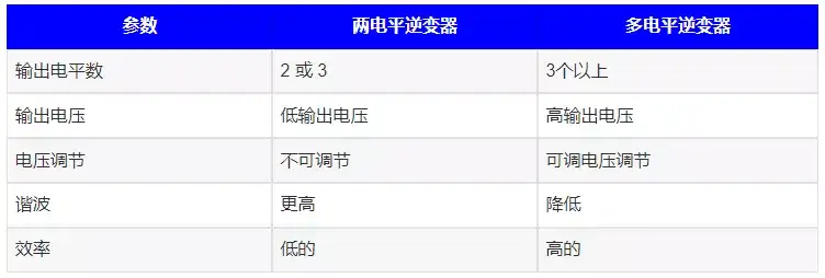
Comparison and Differences Between Two-Level Inverters and Multilevel Inverters
Conclusion:
Due to space limitations, this article only briefly introduces 17 main inverter types. However, there are actually many more classifications of inverters. For example, multilevel inverters can be further divided into flying capacitor inverters (FCMI), diode clamped inverters (DCMI), and cascaded H-bridge inverters.
From a practical application perspective, three-phase inverters are suitable for high-load applications, pure sine wave inverters offer better protection for electrical appliances, and multilevel inverters are the most practical and preferred choice.
.jpg)


 The function of a bi-peak inverter changes with the load. If there is a problem with the grid or when the power from renewable energy sources is sufficient to meet the load, its function will change to stand-alone inverter (it becomes a stand-alone inverter). In this case, the transfer switch disconnects the inverter from the grid.